Mixed Feedback with Audio Output Transformers
Using mixed feedback drive circuits with audio output transformers have two major advantages:
Transformer-caused distortion is reduced (or almost eliminated)
The primary copper resistance of the transformer is eliminated, thus reducing the output impedance correspondingly
Circuit Principles
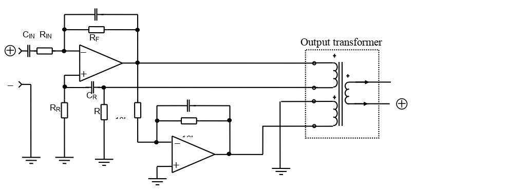
The circuits below illustrate the principles for mixed feedback. In real applications, additional components may have to be added to reach desired performance.
Patent Information
NOTE!
Application of mixed feedback principles for audio output was covered by a German patent DE 29 01 567, with application day 13.1.79.
As far as we understand, the patent has now expired.
Unbalanced Drive